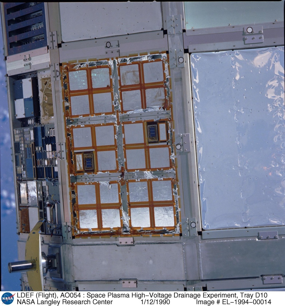
LDEF (Flight), AO054 : Space Plasma High-Voltage Drainage Experiment, Tray D10

LDEF (Flight), AO054 : Space Plasma High-Voltage Drainage Experiment, Tray D10 The Space Plasma High Voltage Drainage Experiment (SP HVD) flight photograph was taken while the LDEF was attached to the Orbiter's RMS arm prior to berthing in the Orbiter's cargo bay. The paint dots on clamp blocks located at the center of the trays right flange and at the right and left ends of the left flange have changed very little from their original white color. The SP HVD experiment consist of two identical sets of experiment hardware mounted in three (3) inch deep LDEF experiment trays, one tray is located in the LDEF position B04 adjacent to the LDEF trailing edge and the other is located at LDEF position D10 adjacent to the LDEF leading edge. Each set of SP HVD experiment hardware, self-contained within the experiment tray, consist of six (6) fiberglass reinforced epoxy modules carrying charged dielectric samples on top and the power supplies and electronics below. Four (4) dielectric samples, Kapton with Vapor Deposited Aluminum on one side (VDA-Kapton), are bonded to each of the fiberglass modules with a silver filled conductive epoxy. The spaces between the dielectric sample covered modules and between the modules and the tray flanges are covered by strips of VDA-Kapton attached with acrylic transfer adhesive and Kapton tape. Each experiment tray also contain two solar cell modules. Power for the experiment is provided by LiSO2 batteries supplied by the LDEF Project. The experiment was assembled using non-magnetic stainless steel fasteners. The SP HVD experiment in this tray was severely degraded by impingement of atomic oxygen during the long exposure to the space environment. Most of the Kapton polyimide material making up the dielectric samples was completely eroded leaving only the 2000-3000 angstrom vapor deposited aluminum layer bonded to the module. The edges of the dielectric surface that survived were taped over by Kapton tape with a silicone adhesive. The Kapton backing eroded leaving the silicone adhesive that protected the Kapton surface beneath. The VDA-Kapton strips used to cover spaces between the modules have degraded substantially and only fragments of the vapor deposited aluminum layer remain attached along the edges. The white paint around the outer edges of the solar cell modules appears to have changed little. Impact craters are visible as black or white specks in many locations on the degraded dielectric surfaces. One of the most noticeable is in the dielectric surface in the upper right corner.
NASA Identifier: L90-10439 S32-78-062
| Date Taken: |
09.23.2009 |
| Date Posted: |
10.18.2012 03:16 |
| Photo ID: |
742207 |
| Resolution: |
1429x1536 |
| Size: |
396.42 KB |
| Location: |
WASHINGTON, DC, US |
| Web Views: |
9 |
| Downloads: |
1 |
PUBLIC DOMAIN

MORE LIKE THIS
CONTROLLED VOCABULARY KEYWORDS
TAGS


LEAVE A COMMENT